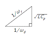
 |
 |
Usage
Input[f] [D]
- R7: L ‐ Inductance [H]
- R8: f0 ‐ Self-resonant frequency of the inductor [Hz]
- R9: fm ‐ L,Q Test frequency of the inductor [Hz]
- x : Cp ‐ Capacitance [F]
- REG y: (fm/fr)1/2
- REG x: fr ‐ Resonant frequency [Hz]
Example
LCR - Rev.1.01, Aug. 8 2011
Input Output
HP 15C - LC resonator replacement for triple speed 15CAppendix A
An example of the electrical characteristics of an actual inductor (TDK SMD Inductors For Signal Line(Wound) NLV Series NLV32)
Inductance
(μH)Inductance
toleranceQ
min.Test frequency L,Q
(MHz)Self-resontant frequency
(MHz)min.DC resistance
(Ω)max.Rated current
(mA)max.Part No. 47 ±5% 30 2.52 15 7 60 NLV32T-470J-☐ 180 ±5% 20 0.796 7 17 60 NLV32T-181J-☐

![[Mail]](/~lyuka/images/mail.gif)


 © 2000 Takayuki HOSODA.